Tutorials
This page gives a brief introduction to the different tools of the “capacity” viewer. In order to use this tool, we advise you to watch the following videos on youtube.
Capacity Viewer
After sending your file for calculation, the result is displayed in the “capacity” viewer which allows you to obtain the volume and see the axis and profile extraction but also to correct some errors (“dpi” value , profile and/or incorrect extracted axis, …). Below we show a screenshot of the viewer after calculating a volume and the two main parts of it: the drawing area where the result is displayed and the toolbar which contains all buttons allowing you to perform an action on the drawing area.
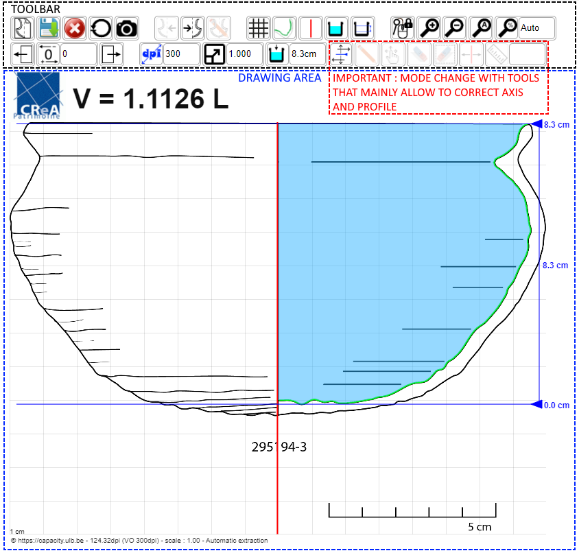
To ensure the calculated volume is as accurate as possible, the following steps should be followed (checklist):
- Verify that the displayed side (left or right) is correct, otherwise change it.
- Erase any incorrect sections of the profile (see the entire extracted profile if it is incorrect).
- Modify the position of the axis by aligning it perfectly with the drawn axis if it was not done automatically.
- Draw/correct the extracted profile by following the profile of the original drawing as closely as possible.
- Adjust the scale as best as possible using a known measurement from the drawing, generally relative to the water height (the difference between the two water levels), for example, using the depth of the container or its height. The alternative would be to use a scale from the drawing with the “measure/slat” tool.
- Check, if possible, that the position of the drawn axis is correct by measuring the distance between the axis and a specific point on the profile, for example, at its opening or bottom, and comparing it to its actual measurement, i.e., half the diameter of the opening or bottom. If this measurement is incorrect, move the axis to obtain this distance, even if it no longer coincides with the axis of the original drawing.
- Adjust the water levels to best measure the volume of interest.
- Finally, save the changes.
Toolbar description
| Buttons allowing file management | |
| New capacity calculation | |
| Save all the modifications to the server (Shortcut : b) | |
| Remove the file definitively | |
| Reset to the last backup | |
| Take a screenshot | |
| Buttons allowing side change | |
| Activate the left profile | |
| Activate the right profile | |
| Enabled if the profile and/or axis has been manualy corrected | |
| Buttons allowing show/hide parts on the drawing area | |
| Show/hide the grid (Shortcut : g) | |
| Show/hide the profile (Shortcut : p) | |
| Show/hide the axis (Shotcut : a) | |
| Show/hide the water (Shortcut : w) | |
| Show/hide the water levels (Shortcut : l) | |
| Buttons allowing drawing size change | |
| Lock/unlock mouse wheel for zoom and image horizonal displacement | |
| Increase image size (Zoom in - Shortcut : +) | |
| Decrease image size (Zoom out - Shortcut : -) | |
| Adapt image size to the wide available view (Shortcut : 0) | |
| Set the image size to the original one (100%) | |
| Enter the image size in purcentage of the original one | |
| Buttons allowing drawing horizontal move | |
| Move image on the left (Shortcut : ←) | |
| Resert image to 0 (Shortcut : Home) | |
| Set the image offset in pixels when the drawing is outside the visible area (negative value for offset on the left and positive on the right) | |
| Move image on the right (Shortcut : →) | |
| Buttons allowing scale and resolution modifications | |
| Reset the resolution (dpi) to the last saved one | |
| Insert the real image resolution in dpi. You can/have to check it with a drawing application like Photoshop or gimp | |
| Reset the scale to the last saved value | |
| Insert the scale, 1cm on the drawing is equal to the real insert value in cm | |
| Reset the water levels to the limits of the currrent profile | |
| Insert the real (water) height between the two blue levels in order to adjust the scale | |
| Buttons allowing actions modifications on the drawing area (mode change) | |
| Move the height levels in order to adjust the volume (Shortcut : m) | |
| Add points to the profile in order to correct or draw it (Shortcut : i) | |
| Move profile points in order to correct it (Shortcut : s) | |
| Delete profile points in order to correct it (Shortcut : d) | |
| Delete selected profile points in order to adjust it (using a rectangle - Shortcut : Delete) | |
| Correct the position of revolution axis (Shortcut : c) | |
| Measure a distance in cm between two points in the drawing (Shortcut : r) | |
| Insert the real value of the measure in cm in order to adjust the scale | |
Calculated Volume Errors
The calculated volume is based on the assumptions that the container is a cylindrical volume of revolution and that the profile and axis drawing are accurate. In reality, these assumptions are rarely verified and therefore contribute significantly to the final volume error.
Regarding drawing errors, it is possible to minimize them somewhat by considering the importance of the different sources of error, from a mathematical point of view,
- A scale error will cause a volume error three times greater. For example, a 1% scale error (e.g., 0.99 or 1.01 scale instead of 1.00) would cause a 3% volume error!
- An error in the position of the axis (its “average” radius) will cause a volume error twice as large. Therefore, a 1mm axis position error for a vase with an “average” radius of 10cm will cause a volume error of approximately 2%!
- Finally, the relative height error will contribute exactly the same volume error. However, this error is closely related to the other two, especially if the scale is adjusted using height. This is also why we recommend verifying the axis position with an actual measurement in checklist point 6.